
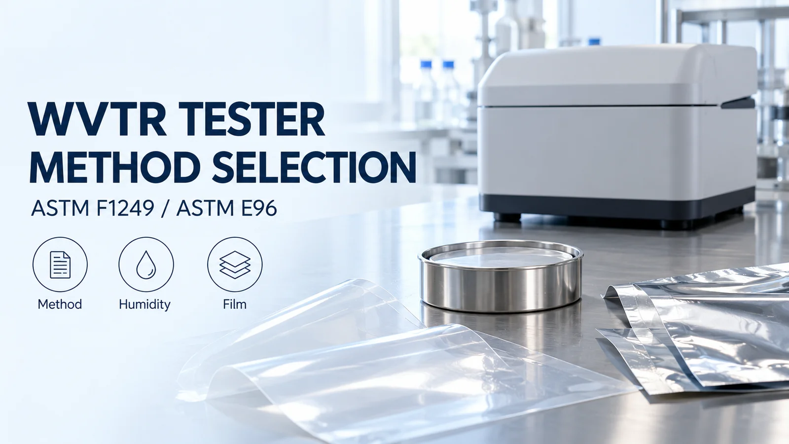
WVTR Tester Method Selection: ASTM F1249 Infrared vs Gravimetric Cup (ASTM E96)
Choose a water vapor transmission rate tester by method, both-side humidity and usable range. Compare ASTM F1249 infrared with ASTM E96 cup testing.
Choose a water vapor transmission rate tester that can measure the target film at the temperature, humidity on both sides and transmission level required by your specification. ASTM F1249 uses modulated infrared sensing; ASTM E96 measures mass change using a desiccant cup or a water cup.
For low-transmission films, start by evaluating an F1249 infrared configuration with demonstrated capability near the expected rate. An E96 cup configuration is a candidate when its mass change can be resolved reliably over a practical test period and its exposure matches the specification. Preserve an existing specified method when checking compliance. For supplier comparisons, match the method, film construction, temperature and both-side humidity, or obtain a documented correlation study covering the materials and conditions being compared.
Scroll horizontally to view all columns if needed. ↔
| Configuration | Measured response | Exposure to identify | Selection question |
|---|---|---|---|
| ASTM F1249, modulated infrared | Water vapor carried to a detector | Humid side, dry carrier side and temperature | Can the configured cell quantify the target rate at the required climate and area? |
| ASTM E96, desiccant cup | Cup assembly gains mass | Chamber → desiccant cup | Is the stable mass gain measurable under the specified dry-cup exposure? |
| ASTM E96, water cup | Cup assembly loses mass | Water cup → chamber | Is the stable mass loss measurable under the specified water-cup exposure? |
The method families are identified in ASTM F1249-25 and ASTM E96/E96M-24a. AMETEK MOCON’s Which WVTR Test Method Is Right for Your Application? (September 2025) discusses transmission level and sensitivity as selection factors. A product described as a “water vapour transmission rate tester” still needs this same method and configuration check.
Start with the film and the specification
Establish the specimen and exposure before choosing the instrument. Gather these four inputs:
- Film identity: sample or lot, layer construction, total thickness and which face meets the humid side.
- Test basis: flat film, converted material or finished package. Keep package results and area-normalized film results distinct.
- Required exposure: temperature, source-side RH and receiving-side RH, with vapor direction identified.
- Method and target: standard number and edition, E96 cup variant if applicable, and the expected WVTR or acceptance limit.
If the specification gives only a WVTR value, retrieve the original laboratory report before selecting a matching test. For the meaning of the units, use the WVTR interpretation guide; for the wider set of material checks, see packaging film performance.
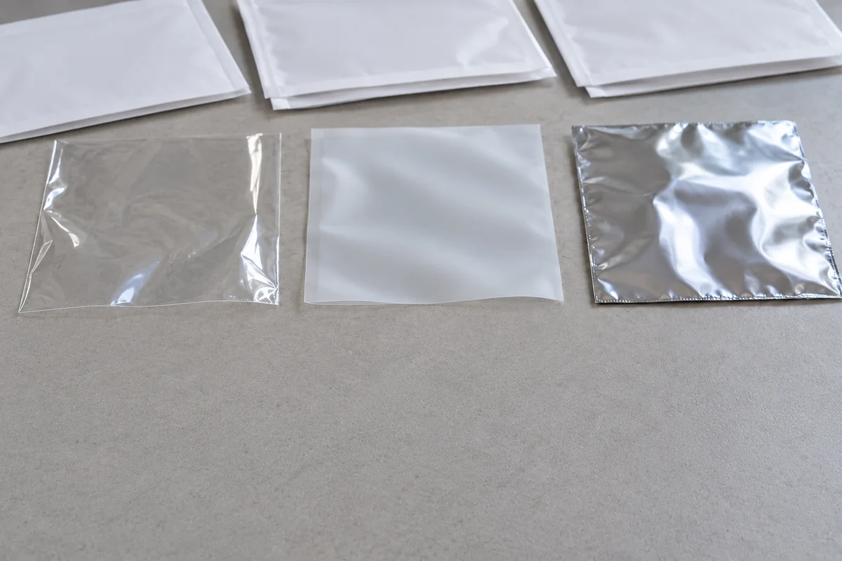
How do infrared and cup measurements differ?
An infrared tester measures vapor reaching a detector; a cup test follows the changing mass of the cup assembly. Both require a defined exposed area and a stable measurement.
F1249: a vapor signal from the receiving stream
In the infrared diffusion-cell arrangement described for AMETEK MOCON’s AQUATRAN 3/34, the film separates a humid chamber from a dry carrier stream. Water passing through the specimen enters that stream and travels to a modulated infrared detector. The instrument relates the detector response to the water-vapor concentration and its reference/calibration basis.
Review the laboratory’s reference verification and stabilized test trend, along with the model and exposed area. An instrument’s “infrared” label alone leaves the method execution unresolved: the report should identify the procedure and edition used.
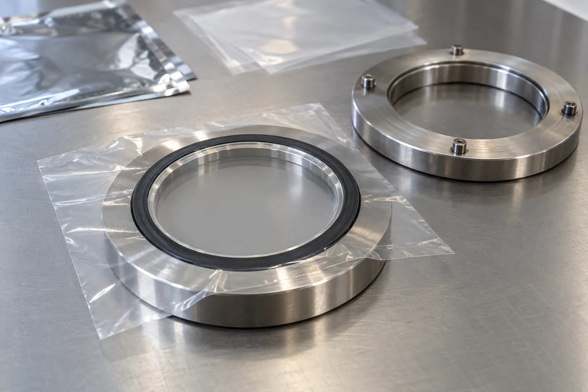
E96: a steady mass-change slope
A desiccant cup gains mass as moisture travels inward and is absorbed. A water cup loses mass as vapor travels outward toward the lower-humidity environment. AMETEK MOCON’s ASTM E96 WVTR Gravimetric Test Method (June 2023) describes both arrangements and their mass-time trends.
The calculation principle is:
WVTR = |steady mass-change slope| ÷ exposed specimen area
With slope in g/day and area in m², the result is g/(m²·day). Use the stable part of the mass-time record. Edge leakage or a changing transient slope can obscure transmission through the film; the laboratory’s procedure supplies the sealing, correction and endpoint checks.
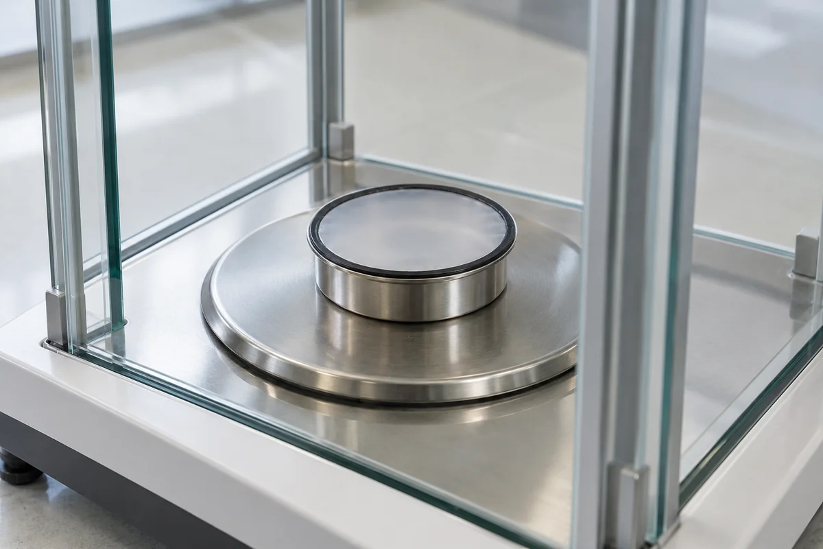
Why must the report give humidity on both sides?
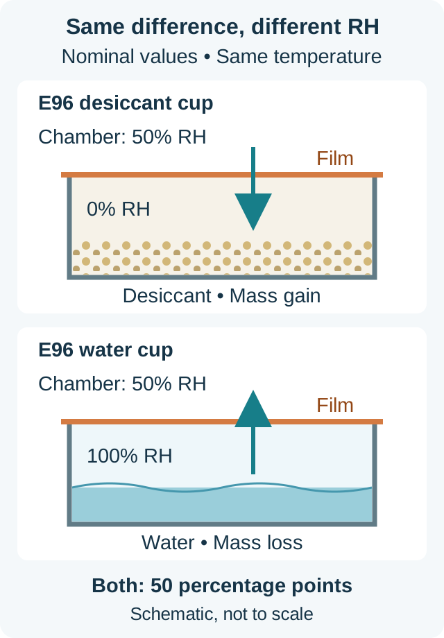
The same RH difference can expose a film to different humidity levels. At the same temperature, MOCON’s June 2023 cup-method note illustrates these nominal conditions:
- Desiccant cup: 50% RH outside → 0% RH inside.
- Water cup: 100% RH inside → 50% RH outside.
Both have a difference of 50 percentage points, yet the water-cup specimen sees a much wetter environment. Moisture-sensitive materials can respond differently; the note gives coated paper swelling as an example. Record the side values and direction, rather than reducing the exposure to a single humidity difference.
ASTM E96/E96M-24a identifies temperature and side-to-side humidity as reporting conditions and cautions against predicting results across conditions or between its two cup methods. Its commonly used climates are options; choose the exposure required by the application or governing specification. For an infrared test, also record the receiving-side carrier conditions instead of inferring an exact measured RH from the word “dry.”
Check usable range, not just display resolution
Evaluate capability near the rate you need to distinguish, using the actual model, exposed area and climate. Display resolution describes the reported increment; repeatability describes variation across repeated measurements.
For a concrete equipment example, AMETEK MOCON publishes the following AQUATRAN 3/34 specifications for its H and L configurations. The range and resolution rows below use the 50 cm² test area.
Scroll horizontally to view all columns if needed. ↔
| Published parameter | Model 3/34 H | Model 3/34 L |
|---|---|---|
| Test range, g/(m²·day), 50 cm² | 0.05–100 | 0.005–100 |
| Resolution, g/(m²·day), 50 cm² | 0.0001 | 0.0001 |
| Repeatability, g/(m²·day) | 0.05 or 2%, whichever is greater | 0.005 or 2%, whichever is greater |
The identical resolution accompanies different published lower limits and repeatability. Ask for the laboratory’s uncertainty or repeatability near your target, including the relevant temperature/RH combination. Check the chosen cell area: the same manufacturer lists different ranges for smaller openings.
Confirm the temperature and humidity as a pair. Labthink’s i-Hydro 7310 product documentation explicitly qualifies its attainable combinations, illustrating why two separate headline ranges are insufficient for selecting an operating point.
For a cup test, the corresponding capability check is whether the stable mass change can be distinguished from weighing variation and other contributions over the planned test period. Very low transmission can require a longer observation period; MOCON’s cup-method note identifies this as a reason to investigate F1249 for high-barrier structures. Obtain a sample-based assessment of time to a stable result before planning throughput.
When can two laboratory reports be compared?
Use matched methods and conditions for a routine supplier comparison. Where methods differ, request a documented correlation study across the relevant films and climates before treating the results as interchangeable. A shared unit alone cannot establish that relationship.
Use this checklist when requesting or reviewing reports:
Scroll horizontally to view all columns if needed. ↔
| Report field | What to align or investigate |
|---|---|
| Specimen | Lot, layer construction, thickness, orientation and film/package basis |
| Procedure | Standard and edition; desiccant or water method for E96; deviations |
| Exposure | Temperature, RH on each side, vapor direction and conditioning |
| Result | Original unit, exposed area, individual results and reported variability |
| Measurement quality | Stable trend and test duration; relevant sealing, blank/leak or reference checks |
| Acceptance | Agreed sampling and decision criterion, with uncertainty addressed near the limit |
This is a practical report-review checklist. For referee testing, ASTM F1249-25 specifically calls for purchaser/seller agreement on sampling, standardization, conditions and acceptance criteria.
If a report lacks one humidity value, obtain the complete exposure. If it says only “E96,” identify the cup configuration. If a proposed comparison changes thickness or humidity, use a new measurement or a validated material-specific relationship: F1249 cautions that simple inverse-thickness and vapor-pressure scaling may fail.
Prepare the laboratory request
Send the film structure and thickness, intended temperature and both-side RH, and the specification’s method number to the laboratory or supplier. Include the required acceptance criterion and ask which configuration, exposed area and measurement-quality evidence will support that decision.
Once the test basis is aligned, use the moisture-barrier selection guide to connect the film result to the product’s protection needs. The finished package and its storage exposure remain part of that packaging decision.
Technical references
- ASTM F1249-25 — modulated infrared method, scope and purchaser/seller test agreement.
- ASTM E96/E96M-24a — gravimetric methods and exposure conditions.
- AMETEK MOCON, ASTM E96 WVTR Gravimetric Test Method, June 2023; Which WVTR Test Method Is Right for Your Application?, September 2025; AQUATRAN 3/34 product specifications.
- Labthink, i-Hydro 7310 product documentation, operating-condition qualification.
Continue reading
Related articles
OTR Tester Setup: ASTM D3985 Dry vs Controlled-Humidity (ASTM F1927) Conditions
Configure an oxygen transmission rate tester for dry ASTM D3985 and humidified ASTM F1927 flat barrier film evaluation.
Seal Strength Tester Setup: ASTM F88 Tail Support (Technique A, B, C) and Acceptance Records
Configure a seal strength tester under ASTM F88/F88M-23 by locking tail support (Technique A, B, or C), strip width, and Clause 10.1 acceptance records.
Hot Tack Tester Setup: Mapping ASTM F1921 Delay Time to Seal-Jaw Window
Set up an ASTM F1921 hot tack tester by aligning delay time, dwell, jaw geometry, and peel speed with your VFFS seal-jaw temperature window.