
Seal Strength Tester Setup: ASTM F88 Tail Support (Technique A, B, C) and Acceptance Records
Configure a seal strength tester under ASTM F88/F88M-23 by locking tail support (Technique A, B, or C), strip width, and Clause 10.1 acceptance records.
Setting up a seal strength tester for seal peel testing requires locking the specimen strip width, tail-holding geometry, grip separation rate, curve calculation window, and specimen failure mode before comparing reports or applying an acceptance limit. Under ASTM F88/F88M-23, the active Standard Test Method for Seal Strength of Flexible Barrier Materials last updated Aug 03, 2023, the test method covers the measurement of the strength of seals in flexible barrier materials. The test may be conducted on seals between a flexible material and another flexible material, a rigid material, or a semi-rigid material, and seals tested in accordance with this test method may be from any source, laboratory or commercial.
Because a portion of the force measured when testing materials may be a bending component and not seal strength alone, ASTM F88/F88M-23 Clause 4.2 recommends consistent use of one tail-holding technique (Technique A, Technique B, or Technique C) throughout a test series. In the ASTM F88/F88M-15 Practice E691 round robin involving 18 laboratories and 1980 samples, testing 1073B Tyvek sealed to 48 ga PET/2 mil LDPE film at 12 in./min produced a Table 3 Grand Average peak seal strength of 0.923 lb/in. under Supported 90°, 1.709 lb/in. under Unsupported, 3.239 lb/in. under Supported 180°, and 1.464 lb/in. under Reverse 180°. Specimen cutters conforming to Clause 5.4 of Test Methods D882 shall be sized to cut strips to 0.984 in. [25 mm], 0.591 in. [15 mm], or 1.00 in. [25.4 mm], and the seal shall be tested at a grip separation rate of 8 to 12 in./min [200 to 300 mm/min].
High-level comparisons of peel, burst, and leak methods belong in the packaging seal strength overview, while the full map of barrier, mechanical, and sealing properties sits in the packaging film performance hub. When a packaging line loads a freshly made seal before it cools, use the hot tack overview and the hot tack tester setup guide instead of a cooled peel test.
How do ASTM F88 Technique A, Technique B, and Technique C change measured seal strength?
Lock the tail-holding technique and grip assignment before comparing two laboratories’ numbers or writing an acceptance limit, because changing how the unsealed tail is supported changes the bending moment recorded by the load cell. ASTM F88/F88M-23 Clauses 4.2.1 through 4.2.3 define the three tail-support configurations:
- In Technique A (Unsupported, Clause 4.2.1), each tail of the specimen is secured in opposing grips and the seal remains unsupported while the test is being conducted.
- In Technique B (Supported 90° By Hand, Clause 4.2.2), each tail of the specimen is secured in opposing grips and the seal remains hand-supported at a 90° perpendicular angle to the tails while the test is being conducted. Under Clause 4.2.2 Note 4, actual gripping of samples by hand is not intended and will influence results; contact is intended to be loose, only preventing tail movement up or down.
- In Technique C (Supported 180°, Clause 4.2.3), for flexible to flexible applications, the least flexible tail is typically supported flat against a rigid alignment plate held in one grip, and the more flexible tail is typically folded 180° over the seal and held in the opposing grip. In rigid and semi-rigid applications under Clause 4.2.3, the package structure may be maintained for the least flexible side, with this structure gripped or fixtured.
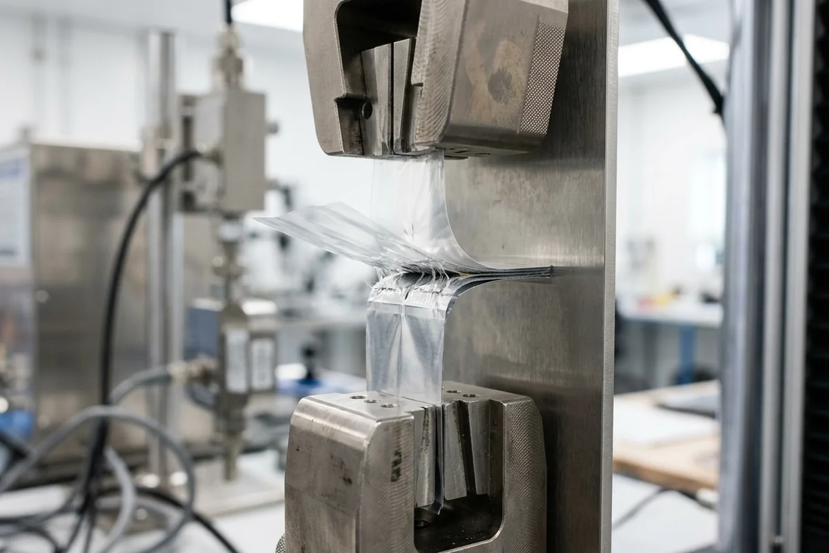
Under ASTM F88/F88M-23 Clause 4.2.3 Note 5, properties of some flexible materials may cause movement or flipping of the tail throughout the course of the test, which has potential to impact the measured strength and should be reported with results. Clause 4.2.3 Note 6 adds that test method validation should account for use of fixtures or alignment plates as well as determination of which material is placed into which grip, referencing Guide F3263 for guidance on test method validation. DDL Inc. notes in its ASTM F88 engineering overview that Technique A and Technique C are the two most commonly used techniques and that Technique C can give almost two times the result of Technique A.
In ASTM F88/F88M-15 Clause 11.1, a round robin was conducted using Practice E691 as a guide, involving 18 laboratories measuring a total of 1980 samples distributed over three test groups of six laboratories each, with precision concepts r and R applying to test results that are averages from testing 10 to 30 specimens. Appendix X1.1.3 of ASTM F88/F88M-15 states that splitting the round-robin data into n=30 and n=10 resulted in overall average measured values differing by less than 0.1 #/in., and Table X1.1 Note 3 defines Reverse 180° as incorrect loading where the most flexible material is supported 180° and the least flexible material is bent back.
Scroll horizontally to view all columns if needed. ↔
| Round-robin series & material pair | Test configuration & speed | Table 3 Grand Average in lb/in. | Table 4 Grand Average in N/25.4 mm |
|---|---|---|---|
| Series A: Heat Seal Coated 50# Basis Weight Paper to 48 ga PET/2 mil LDPE film | Supported 90°, Unsupported at 12 in./min, and Unsupported at 8 in./min (Maximum) | 0.957 (Supported 90°), 1.424 (Unsupported at 12 in./min), and 1.417 (Unsupported at 8 in./min) | 4.2569 (Supported 90°), 6.3343 (Unsupported at 12 in./min), and 6.3031 (Unsupported at 8 in./min) |
| Series B: Uncoated 1073B Tyvek to 48 ga PET/2 mil LDPE film (90° and Unsupported) | Supported 90° and Unsupported at 12 in./min (PEAK and AVG) | 0.923 (PEAK 90°), 0.684 (AVG 90°), 1.709 (PEAK Unsupported), and 1.453 (AVG Unsupported) | 4.1057 (PEAK 90°), 3.0426 (AVG 90°), 7.6020 (PEAK Unsupported), and 6.4633 (AVG Unsupported) |
| Series B: Uncoated 1073B Tyvek to 48 ga PET/2 mil LDPE film (180° and Reverse 180°) | Supported 180° and Reverse 180° at 12 in./min (PEAK and AVG) | 3.239 (PEAK 180°), 2.990 (AVG 180°), 1.464 (PEAK 180° Reverse), and 0.936 (AVG 180° Reverse) | 14.4078 (PEAK 180°), 13.3002 (AVG 180°), 6.5122 (PEAK 180° Reverse), and 4.1635 (AVG 180° Reverse) |
| Series C: 3 mil Film and 5 mil Foil at 12 in./min | Unsupported versus Supported 180° (Maximum) | 1.695 (3 mil Film Unsupported), 3.463 (3 mil Film 180°), 1.209 (5 mil Foil Unsupported), and 4.569 (5 mil Foil 180°) | 7.5397 (3 mil Film Unsupported), 15.4042 (3 mil Film 180°), 5.3779 (5 mil Foil Unsupported), and 20.3239 (5 mil Foil 180°) |
Comparing the Series B and Series C Grand Averages shows why grip assignment and tail support must be written into every specification rather than left to operator preference. When operators reverse the webs in Series B so that the more flexible film is backed by the alignment plate and the stiffer web is folded back, the measured peak force drops from the Supported 180° value to the Reverse 180° value in the table above.
How to normalize strip width and force units across seal peel testing reports
Convert every seal strength report onto a matched unit-width basis before comparing supplier data sheets or lab certificates. ASTM F88/F88M-23 Clause 1.6 states that values stated in either SI units or inch-pound units are to be regarded separately as standard, and combining values from the two systems may result in non-conformance with the standard. When reviewing multi-property data sheets across suppliers, pair this normalization check with our guide on how to compare flexible packaging film specifications.
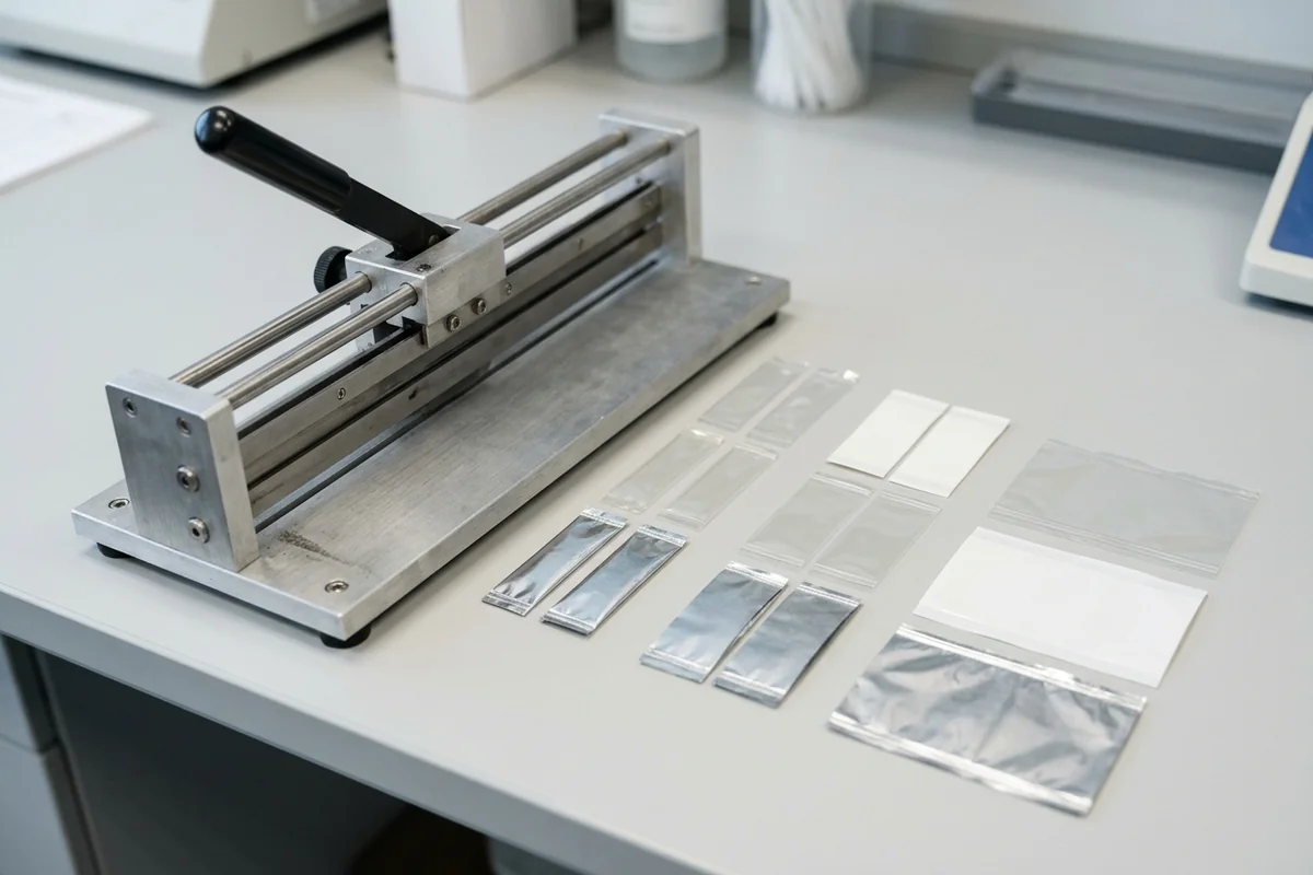
In ASTM F88/F88M-15 Clause 6.2, the specimen cutter, conforming to the requirements of Clause 5.4 of Test Methods D882, shall be sized to cut specimens to a width of 0.984 in. [25 mm], 0.591 in. [15 mm], or 1.00 in. [25.4 mm]. Intertek Testlopedia similarly notes that in ASTM F88 seal strength testing a rectangular specimen of width 25 mm, 15 mm, or 1.00 inch is used, and the seal may be unsupported (technique A), at 90º to the pull direction (technique B), or at 180º to the pulling direction (technique C). Mecmesin states that ASTM F88 test preparation cuts strips to a width of 15 mm, 25 mm, or 25.4 mm perpendicular to the seal and 75 mm plus the width of the seal in length, conditioned if required in accordance with ASTM E 171.
Per NIST Special Publication 811 Appendix B.8, to convert from inch (in) to meter (m), multiply by 2.54 E-02, and to convert from inch (in) to centimeter (cm), multiply by 2.54 E+00. To convert from pound-force (lbf) to newton (N), multiply by 4.448 222 E+00, and to convert from pound-force per inch (lbf/in) to newton per meter (N/m), multiply by 1.751 268 E+02. To convert from kilogram-force (kgf) to newton (N), multiply by 9.806 65 E+00.
For a worked example, assume a seal strength specification of 1.0 lbf/in. Scaling that 1.0 lbf/in (4.448222 N per 25.4 mm strip width, or 175.1268 N/m) to a 15 mm strip width multiplies by the width ratio 15 / 25.4 (0.5906, the reciprocal of 25.4 / 15 = 1.693), yielding 2.6269 N per 15 mm strip width.
How to configure grip separation rate, initial grip distance, and commercial testers
Set the tensile testing machine’s jaw separation speed and initial grip spacing to control the true rate of peel at the seal line and prevent leg stretching from distorting the curve. Under ASTM F88/F88M-15 Clause 6.1, the tensile testing machine shall be of the constant rate-of-jaw-separation type, equipped with a weighing system that moves a maximum distance of 2 % of the specimen extension within the range being measured. Under ASTM F88/F88M-15 Clause 9.6, the seal shall be tested at a rate of grip separation of 8 to 12 in./min [200 to 300 mm/min].
Annex A1.4 of ASTM F88/F88M-15 explains the kinematic relationship between crosshead travel and seal peeling: whenever separation of the grips holding the test strip is translated completely into peeling of the seal, an increase in grip separation of X cm causes an advance of the failure line into the seal of 0.5X cm, so the ideal peel rate is 1/2 of the grip separation rate. At a grip separation rate of 200 to 300 mm/min, the ideal seal peel rate is 100 to 150 mm/min.
Under Annex A1.2 of ASTM F88/F88M-15, if the test strip stretches or delaminates during grip travel, the rate of peel will be lower than that calculated from the grip separation rate, and the rate of peel is then no longer controlled by the machine. To limit unsealed leg extension at the start of the pull, ASTM F88/F88M-15 Clause 9.3 sets the recommended initial distance between grips (initial unconstrained specimen length) at 0.39 in. [10 mm] for fin and hot-wire seals in highly extensible materials (100 + % elongation at seal failure), 1.0 in. [25 mm] for less extensible materials, and X + 10 mm for lap seals.
Scroll horizontally to view all columns if needed. ↔
| Manufacturer | Published instrument or cutter models | Published capability or specification |
|---|---|---|
| Mecmesin | FPT-H1 horizontal Friction, Peel and Tear tester | Measures flexible seal strength according to ASTM F88 or EN 868-5 standards with Emperor software |
| Thwing-Albert | VantageNX, FP-2265, MAP4 software, CeraTek AS/1 (12″ and 24″) and ASL/1 | Supports ASTM F88 seal strength testing and produces repeatable laboratory seals |
| Thwing-Albert | MTT Strip Cutter and JDC Precision Sample Cutter | MTT prepares 1″ or 15 mm strips within 0.5% accuracy; JDC holds ±0.001″ accuracy from 0.125″ to 3″ wide in 10″, 12″, and 16″ lengths |
| Labthink | XLW (PC) Auto Tensile Tester | Tests plastic films and flexible packaging materials with a precision of 0.5% of full scale; Labthink’s ASTM F88 method overview pulls one-inch wide samples cut perpendicular to the seal at a constant speed (usually 12 inches/minute) |
| Testronix Instruments | TX PBT 200 and TX PBTC 300 | Digital model TX PBT 200 and computerized model TX PBTC 300 with a 20 Kgf capacity |
How to set ASTM F88 acceptance criteria: Peak vs. central-80% Average force and failure modes
Establish acceptance limits from packaging process validation, target opening behavior, and observed specimen failure mode rather than adopting an arbitrary force number. Under ASTM F88/F88M-23 Clause 4.1, seal strength is a quantitative measure for use in process validation, capability, and control, and at times it is desirable to have an upper limit to the strength of the seal to facilitate opening. Clause 4.1 Note 1 states that seal separation is indicative of the area of the package being sampled and does not take into account simulation of a user interfacing with an entire package during the opening process.
ASTM F88/F88M-23 Clause 4.1 Notes 2 and 3 distinguish lower and upper specification limits:
- Under Clause 4.1 Note 2, lower seal strength specifications are typically utilized to provide assurance of package closure, which can contribute to seal integrity.
- Under Clause 4.1 Note 3, upper seal strength specifications are typically utilized to limit the amount of force required to open a package and are typically limited to seals that are intended to be peeled by the end user.
DDL Inc. states that minimum specifications from seal strength derive from process validation (low, nominal, and high) rather than an arbitrary one pound specification. Boulder Package Testing states that ASTM F88 is referenced in ISO 11607-1 and ISO 11607-2 for seal strength evaluation, and that there is no single universal acceptable seal strength value because acceptance criteria are set by the manufacturer based on packaging design, sealing process capability, and risk analysis (noting typical heat-sealed pouch peel strengths fall in the 1.0 to 4.0 lbf/in range). For medical device packaging and peelable lidding foil structures, both lower closure assurance and upper peelability limits apply.
Under ASTM F88/F88M-23 Clause 4.1.1, the maximum seal force is important information, and for some applications, average force to separate the seal may be useful, and in those cases also should be reported. In ASTM F88/F88M-15 Terminology, maximum seal strength (Clause 3.1.3) is defined as the maximum force per unit width of seal required to separate progressively a flexible material from a rigid material or another flexible material, under the conditions of the test, while average seal strength (Clause 3.1.1) is defined as the average force per unit width of seal required to separate progressively a flexible material from a rigid material or another flexible material, under the conditions of the test. Clause 3.1.2 defines flexible as indicating a material with flexural strength and thickness permitting a turn back at an approximate 180 degree angle.
When calculating average peel force, ASTM F88/F88M-15 imposes three rules:
- Under Clause 3.1.1.1, the initial ramp-up from zero to the force level required to peel the seal and the return to zero following complete failure should not be included in the calculation of average strength.
- Under Clause 3.1.1.1, the amount of data actually discarded on each end of the measured seal-profile curve must be the same for all tests within any set of comparisons of average seal strength.
- Under Clauses 9.8 and 9.8.1, if the test strip peels apart in the seal area by adhesive failure, cohesive failure, or delamination, the average peel force should be measured by the testing machine, and Fig. 3 illustrates an algorithm using data only from the central 80 % of the curve. Mecmesin states that in ASTM F88/F88M testing, average force to open the seal is calculated over an 80% zone situated between the data markers of 10% - 90% of the peeling distance, discarding the first 10% and the last 10% of the force vs. displacement curve.
Conversely, under ASTM F88/F88M-15 Clause 9.8.2, if the test strip does not peel significantly in the seal area and failure is largely by breaking, tearing, or elongation of the substrate material, average force to failure may have little significance in describing seal performance and should not be reported.
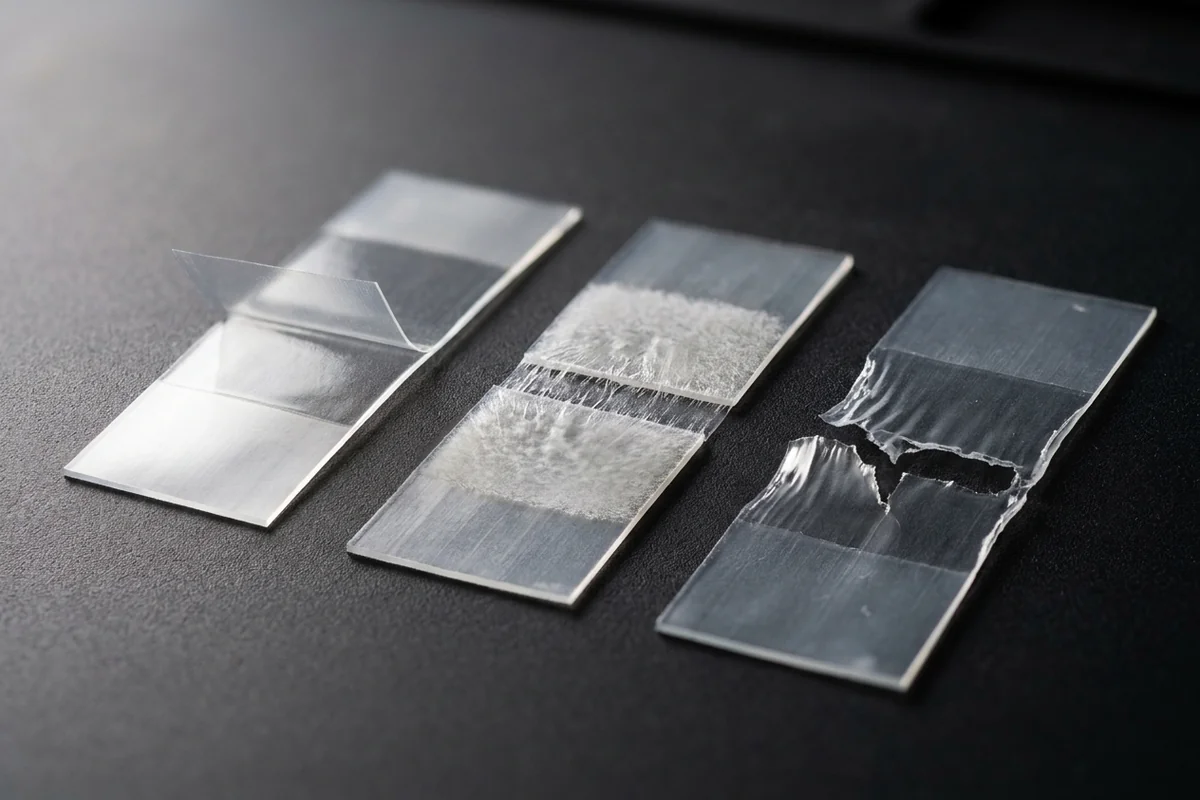
Under ASTM F88/F88M-15 Clause 10.1.14, visual determination of all modes of specimen failure observed shall be reported; suggested classifications are adhesive failure of the seal (peel), cohesive failure of the material, break or tear of material in seal area or at seal edge, delamination of surface layer(s) from substrate, elongation of material, and break or tear of material remote from seal.
Keep ASTM F88 strip peel testing separate from whole-package pressurization, leak detection, laboratory seal preparation, and warm-seal hot tack standards:
- ASTM F2029-16(2021) covers laboratory preparation of heat seals using hot-bar or impulse sealing methods to determine heat sealability as measured by Test Method F88; it does not cover production equipment validation or hot tack testing under Test Methods F1921. Use these laboratory heat seals when mapping seal initiation temperature.
- ASTM F1921/F1921M-12(2023) covers instrumented laboratory measurement of the strength of heatseals immediately after a seal has been made and before it cools to ambient temperature (hot tack strength), excluding non-instrumented manual procedures.
- ASTM F1140/F1140M-13(2025) covers internal pressurization burst and creep testing of unrestrained packages and states that these test methods do not necessarily provide correlation with actual package seal strength as measured using Test Method F88. Labthink states that for package creep testing under ASTM F1140 (using instruments such as the LSSD-01 or C660M Leak and Seal Strength Tester, based on ISO 11607, ASTM F1140 & ASTM F2054), the suggested test pressure is about 80% of burst pressure.
- ASTM F2054/F2054M-13(2024) covers internal air pressurization burst testing of flexible package seals within restraining plates, noting it cannot measure package seal uniformity or overall package integrity and may not correlate with Test Methods F1140 or F88.
- ASTM F2096-11(2019) covers detecting gross leaks in tray and pouch packaging by internal pressurization (bubble test) with a method sensitivity down to 250 μm (0.010 in.) with an 81 % probability to detect substrate holes and channels.
- Under ASTM F88/F88M-23 Clause 1.5, Test Method F88 differs from Test Method F2824, which measures mechanical seal strength while separating an entire lid (cover/membrane) from a rigid or semi-rigid round container.
ASTM F88 Clause 10.1 acceptance record and laboratory handoff checklist
Before running a compliance series or reconciling two laboratories’ seal peel reports, verify conditioning and complete the mandatory report fields. Under ASTM F88/F88M-15 Clause 8.1, in the absence of information showing that heat seal strength stability is reached in shorter times, sealed materials are conditioned and tested in accordance with Specification E171 with a minimum conditioning time of 40 h or longer.
Under ASTM F88/F88M-15 Clauses 10.1.4 through 10.1.12, the test report shall include ambient temperature and humidity, grip separation rate, initial grip separation distance, seal width, force values to three significant figures, tail-holding technique (Technique A, B, or C) and fixtures, which material is clamped in each grip for two different materials, and number of specimens tested. Under Clauses 10.1.15 and 10.1.16, the test report shall include maximum force encountered at failure (expressed preferably in Newtons/meter or lbf/in. of original specimen width, with Gmf/in. and lbf/in. commonly used) and, if average peel force is reported, a statement of the method or algorithm used to calculate the average.
Scroll horizontally to view all columns if needed. ↔
| Report field | Requirement to record on the laboratory sheet |
|---|---|
| Seal origin & conditioning | Laboratory or commercial seal source (Clause 1.3); conditioned per Specification E171 for 40 h minimum unless stability is shown in shorter times (Clause 8.1) |
| Ambient test environment | Ambient temperature and humidity during testing (Clause 10.1.4) |
| Specimen strip width & seal width | Cutter width of 0.984 in. [25 mm], 0.591 in. [15 mm], or 1.00 in. [25.4 mm] (Clause 6.2) and seal width (Clause 10.1) |
| Tail-holding technique & grip assignment | Technique A, B, or C, fixtures used, and which material is clamped in each grip for two different materials (Clauses 10.1.4 to 10.1.12) |
| Machine speed & initial grip distance | Grip separation rate of 8 to 12 in./min [200 to 300 mm/min] (Clause 9.6) and initial distance of 0.39 in. [10 mm], 1.0 in. [25 mm], or X + 10 mm (Clause 9.3) |
| Sample count & significant figures | Number of specimens tested and force values to three significant figures (Clause 10.1) |
| Force output & averaging algorithm | Maximum force in Newtons/meter or lbf/in. (or Gmf/in.), plus average peel force algorithm such as the central 80 % zone (Clauses 9.8.1, 10.1.15, 10.1.16) |
| Visual failure modes observed | Adhesive failure of the seal (peel), cohesive failure, break or tear in seal area or at seal edge, delamination, elongation, or break/tear remote from seal (Clause 10.1.14) |
When preparing a seal strength specification or auditing a laboratory test report, confirm four items in writing: the exact specimen strip width, the tail-holding technique and grip orientation for dissimilar webs, whether acceptance applies to peak force or central-window average peel force alongside the required failure mode, and the governing specification clauses for conditioning, seal preparation, and whole-pack verification.
Continue reading
Related articles
Hot Tack Tester Setup: Mapping ASTM F1921 Delay Time to Seal-Jaw Window
Set up an ASTM F1921 hot tack tester by aligning delay time, dwell, jaw geometry, and peel speed with your VFFS seal-jaw temperature window.
OTR Tester Setup: ASTM D3985 Dry vs Controlled-Humidity (ASTM F1927) Conditions
Configure an oxygen transmission rate tester for dry ASTM D3985 and humidified ASTM F1927 flat barrier film evaluation.
WVTR Tester Method Selection: ASTM F1249 Infrared vs Gravimetric Cup (ASTM E96)
Choose a water vapor transmission rate tester by method, both-side humidity and usable range. Compare ASTM F1249 infrared with ASTM E96 cup testing.