
Packaging Seal Strength: Testing and Specifying Seals
Packaging seal strength is how much force a heat seal resists before it opens. Learn ASTM F88 peel, burst and leak tests, failure modes and how to write a spec.
A strong seal can still leak through a wrinkle or trapped product. Packaging seal strength is the force a seal can resist before it separates, usually measured by peeling a strip of the sealed area apart in a tensile tester. It measures resistance to separation; whole-pack loading and integrity need their own tests. For peelable packs, opening force is also a design input. The temperature at which seals first form is covered under seal initiation temperature.
Scroll horizontally to view all columns if needed. ↔
| Test object | Output to report | Question answered |
|---|---|---|
| Peel; sealed strip | Force with strip width, e.g. N/15 mm | How much force separates this seal? |
| Burst; pressurized package | Failure pressure, e.g. kPa | At what pressure does this pack fail? |
| Creep; package at set pressure | Hold pressure and time, e.g. kPa and s | Does it withstand the specified pressure/time? |
| Leak; package under selected method | Detection result and method conditions | Is a leak detectable at this sensitivity? |
Units are reporting examples, not pass limits. Common mistake: Treating a peel-force pass as evidence that the whole pack is leak-free.
Peel strength: ASTM F88
ASTM F88 (F88/F88M-23) is the standard test method for seal strength of flexible barrier materials. A strip is cut across the seal, the two unsealed tails are gripped in a tensile tester and pulled apart, and the force is recorded. The main variables are:
- Specimen width. Strips are commonly 15 mm or 25.4 mm (1 inch) wide, and results are reported as force per width, such as N/15 mm or N/25.4 mm. The width must be stated, because a seal strength number means nothing without it.
- Peel techniques. F88 describes three ways of holding the specimen. Technique A, unsupported: each tail is held in opposing grips and the seal is left free while it peels. Technique B, supported 90° by hand: the seal is hand-supported at 90° to the tails, with loose contact that only stops the tail moving up or down, not a fixture. Technique C, supported 180°: for flexible-to-flexible samples the less flexible tail is typically held flat against a rigid alignment plate in one grip and the more flexible tail is folded back 180° over the seal into the opposing grip. The standard notes that part of the measured force can be bending rather than seal strength and recommends one technique throughout a test series, so state the technique and use the same one when comparing materials.
- Speed and conditioning. Crosshead speed and the temperature and humidity at which samples are conditioned and tested should be stated and kept constant.
- Max versus average. The curve of force against distance can be reported two ways: the maximum force (the peak) and the average force over the peel. Peak values suit a “does it hold” question. Average values describe a steady peel better, which matters for a peelable seal where the feel when opening is part of the design. State which one the specification uses.
ASTM F2029 (F2029-16(2021)) describes how to make laboratory heat seals under controlled temperature, dwell and pressure, which is how seal curves and sealant comparisons are generated. Lab seals characterize the material under controlled conditions; production seals show the process result.
Takeaway: Keep these sample sources separate and report technique, width, speed and conditioning with the force curve.
Burst and creep tests
Peel tests look at a small strip. Burst and creep tests load the whole seal with internal pressure.
- ASTM F1140 (F1140/F1140M-13(2025)) covers internal pressurization failure resistance of unrestrained packages. The pack is inflated and expands freely until the seal or film fails, or it is held at a set pressure for a period (a creep test).
- ASTM F2054 (F2054/F2054M-13(2024)) is the restrained version, in which the pack sits between plates that limit its expansion. The plates change the stress distribution around the seal; this is not a direct simulation of a shipping case.
Burst gives a peak pressure, and creep tells you whether a seal slowly opens under a sustained load. These tests are useful for pouches that are squeezed or stacked, for products that outgas, and for packs that see pressure changes in transit.
Takeaway: Compare pressure results only with the same restraint, pack size and pressurization conditions; record hold pressure and duration for creep separately.
Leak tests in brief
A seal can be strong and still leak, for example where a wrinkle or a bit of product leaves a channel. Leak tests check integrity rather than force.
- ASTM F2096 (F2096-11(2019)) is the gross leak test by internal pressurization (bubble test): the pack is pressurized and watched for bubbles under water.
- ASTM D3078 (D3078-02(2021)e1) detects leaks by bubble emission in a vacuum chamber, where the pack is submerged and bubbles show where gas escapes.
Other methods exist for fine leaks, such as dye or tracer-gas methods, and the sensitivity varies. For sterile barrier packs, ISO 11607 is the broader framework, and its requirements depend on the destination market. Medical device packaging gives the context.
Takeaway: Select an integrity method and detection capability for the package risk, separately from the strength limit.
Peelable seals versus lock seals
Seals fall into two broad design classes.
Scroll horizontally to view all columns if needed. ↔
| Feature | Peelable seal | Lock (permanent) seal |
|---|---|---|
| Purpose | Opens cleanly by hand without tearing the film | Holds through handling and cannot be opened without tearing |
| Typical use | Lidding on trays and cups, easy-open pouches, medical device packs | Most pouches, bags and stick packs |
| Failure on opening | Interface separates (adhesive) or the sealant layer splits (cohesive) | Film tears, or the seal holds while the web fails |
| Specification | Minimum and maximum peel force, consistent peel | Minimum seal strength, often with a requirement that failure occurs in the film |
| Main risk | Too weak and leaks in transit, too strong and tears when opened | Too weak and opens under load |
Peelable systems use a sealant engineered to separate at a controlled force over a broad span of seal conditions, which is why they have both a minimum and a maximum. Lock seals are the common case on stand-up pouches, pillow bags and flow wrap, where a strong, tear-through seal is the aim. The lidding foil page covers peelable lid systems for containers.
Failure modes
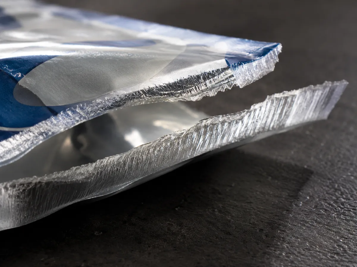
Record the observed failure location alongside the force curve. The photo above illustrates inspection; it does not establish which mechanism occurred.
Scroll horizontally to view all columns if needed. ↔
| Failure-location key, schematic | Observation to record |
|---|---|
| Sealant A / joining interface / sealant B | Adhesive: separation at the original sealed interface |
| Sealant A / within sealant / sealant B | Cohesive: sealant splits, with material on both sides |
| Outer film / laminate bond / sealant | Delamination: failure between structural layers |
| Film beside seal / intact seal | Film break: web tears before the seal separates |
| Wrinkle, channel or trapped product | Record location and verify package integrity separately |
This is a text schematic, not to scale, with no measured force implied. A delamination result alone does not identify whether cure, contamination or another cause is responsible. Use laminate bond checks when structural layers separate.
Takeaway: Match the observed mode to the intended opening behavior and agreed acceptance criteria.
Writing a seal specification without inventing numbers
Define the filling, handling and opening hazards first. Set limits from qualified package trials and intended opening behavior, not a copied supplier number. Complete this record for each sample series:
Scroll horizontally to view all columns if needed. ↔
| Specification field | Value or record to fill in |
|---|---|
| Structure, lot and seal location | ___ |
| Sample source and age | Laboratory or production; time since sealing: ___ |
| Specimen width and F88 technique | Width: ___ mm; A/B/C: ___ |
| Test speed and conditioning | ___; temperature/RH/time: ___ |
| Force output and limits | Peak / average / both; force with width; limits: ___ |
| Failure mode | Expected: ___; observed: ___ |
| Integrity test and sampling | Method / detection capability / sample plan / result: ___ |
| Package loading test, if required | Burst or creep method / conditions / acceptance: ___ |
| Sealing process window | Qualified temperature / dwell / pressure: ___ |
For fast vertical lines, also check hot tack while the seal is warm.
Takeaway: Approve the strength, failure mode and integrity records together before treating a seal as qualified.
Use comparing film specifications to keep supplier test conditions consistent.
Sources and method
The official ASTM pages linked in the test sections define strip strength, controlled laboratory sealing, package pressurization and gross-leak detection. The failure-location key and blank record organize those distinctions; they are not test results or universal acceptance limits. Public scopes checked 9 October 2026. Use the agreed full standard edition for test execution.

Continue reading
Related articles
Hot Tack in Packaging Films: What It Is and Why It Matters
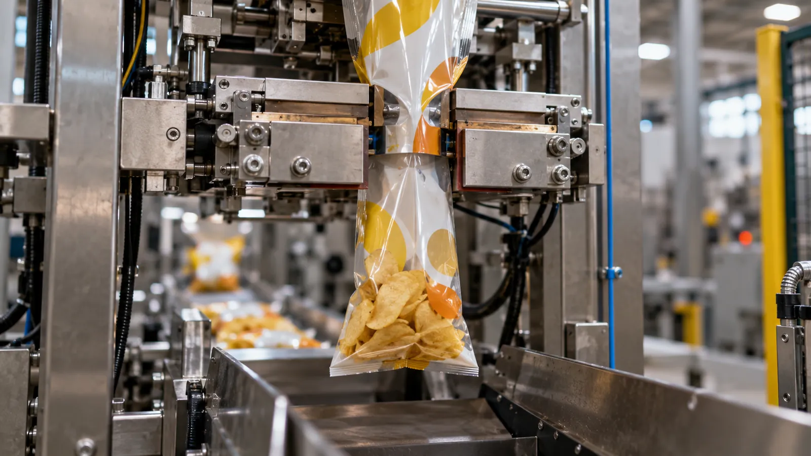
Hot tack packaging performance is the strength of a heat seal while it is still molten. Learn the ASTM F1921 test, the hot tack curve and how it affects VFFS lines.
Seal Initiation Temperature (SIT): What It Is and How It's Measured
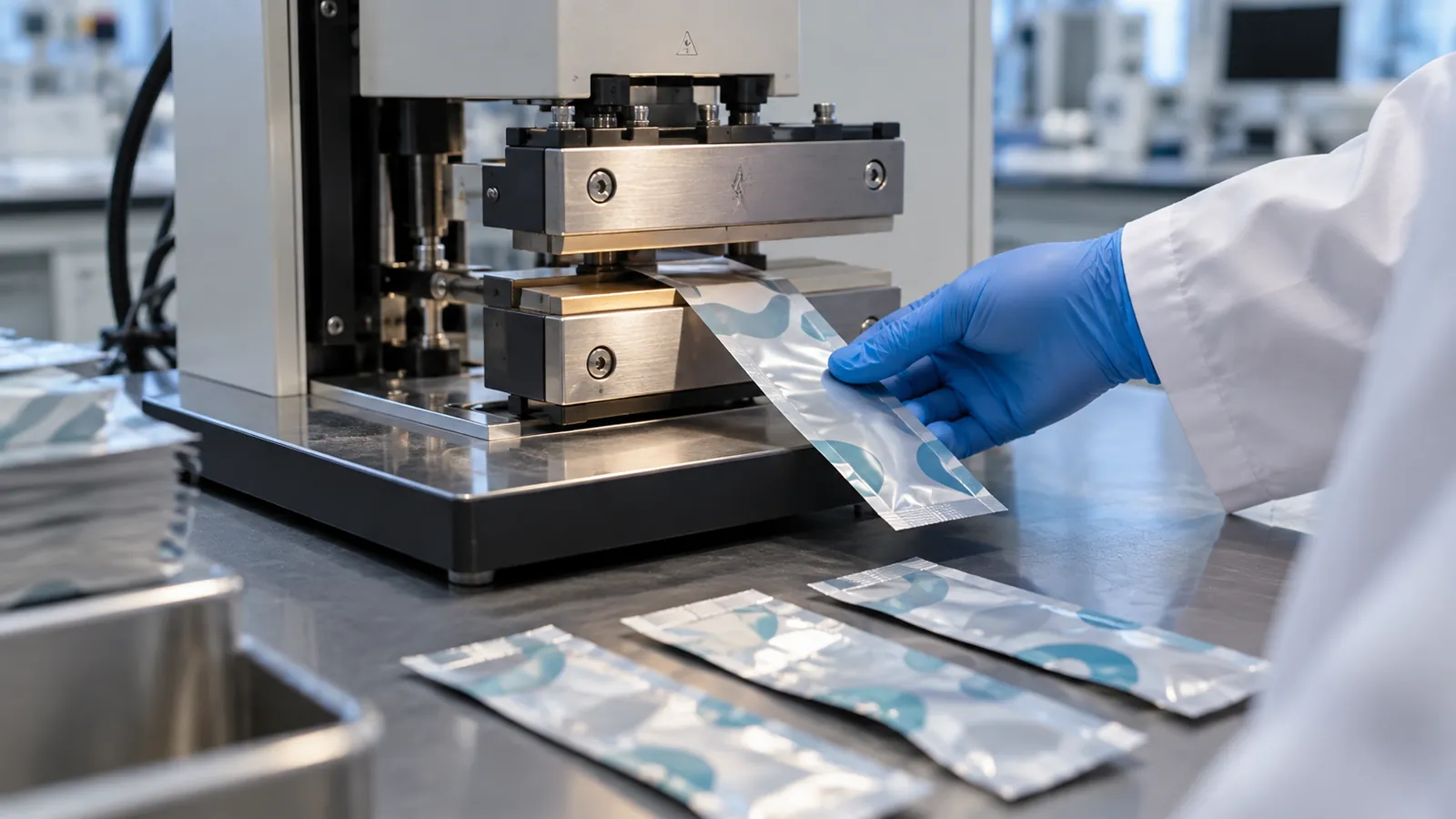
Seal initiation temperature is the lowest sealing temperature at which a heat seal reaches a defined minimum strength. Learn how SIT is measured and used.
Oxygen Transmission Rate (OTR): Units, Test Methods and How to Read It
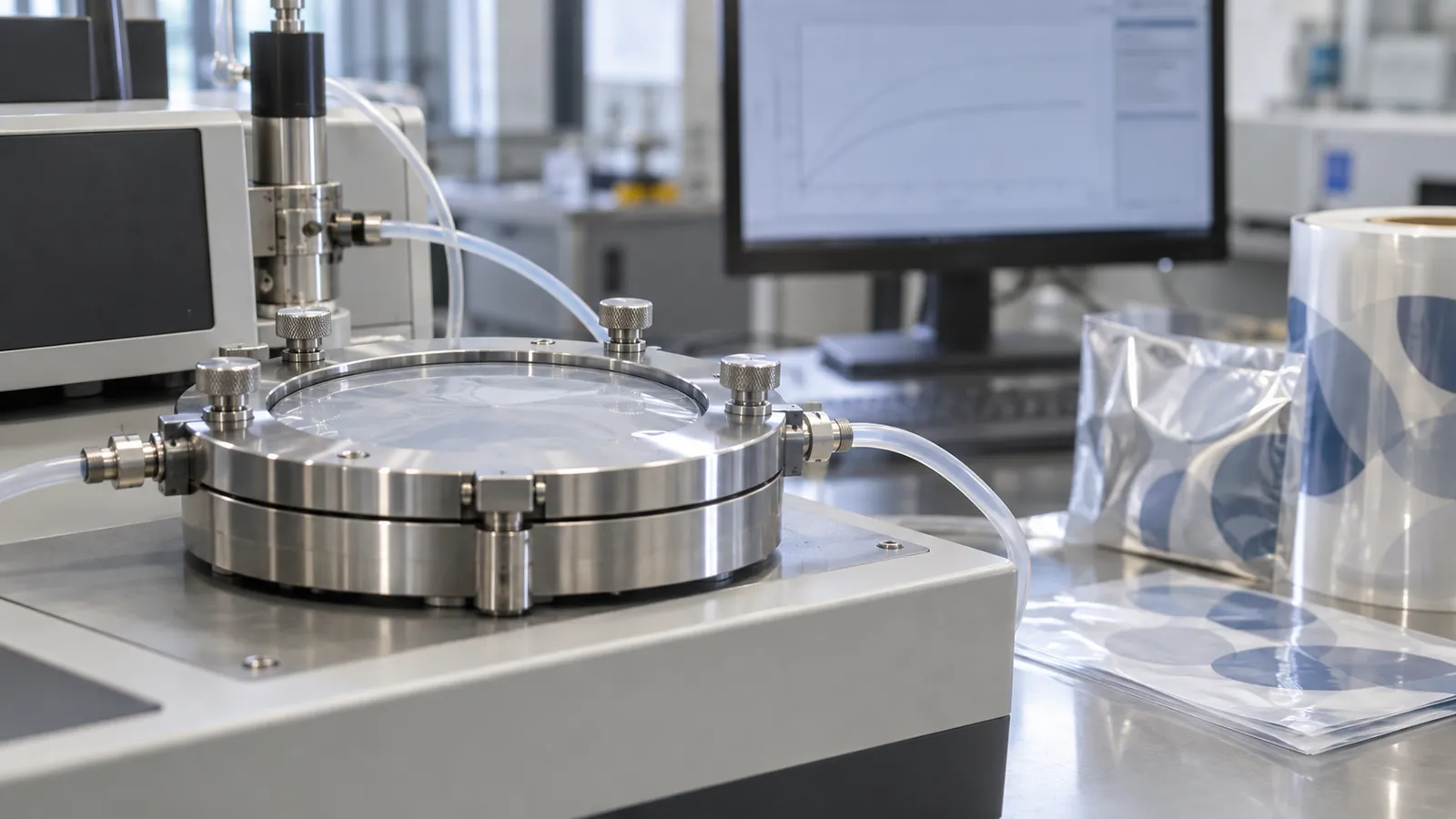
Oxygen transmission rate (OTR) measures how much oxygen passes through a film. Learn the units, test methods, conditions and how OTR relates to shelf life.