Hot Tack Tester Setup: Mapping ASTM F1921 Delay Time to Seal-Jaw Window
Set up an ASTM F1921 hot tack tester by aligning delay time, dwell, jaw geometry, and peel speed with your VFFS seal-jaw temperature window.
Configure a hot tack tester by locking its delay time, closed-jaw dwell, bar pressure, and peel speed to the exact moment the packaging line loads a fresh seal. Running an ASTM F1921 hot tack test at an unaligned delay time or mismatched bar geometry mispredicts the usable jaw window and causes bottom seals to split or leak under product drop.
To map an ASTM F1921/F1921M-12(2023) hot tack curve to a production seal-jaw window, set laboratory dwell time to the machine’s actual closed-jaw contact interval and set delay time to the measured interval from horizontal jaw opening to first product impact. Both ASTM F1921 Method A (cooling curve across cooling intervals) and Method B (maximum warm-seal force after a selected delay time across a temperature sweep) require automated, instrumented machines with zero operator influence. Because commercial instruments differ in standard seal-bar dimensions (such as 50 x 5 mm on Thwing-Albert’s J&B 5000MB, 100 x 5 mm on Labthink’s HTT-L1, and 50 x 10 mm on Cell Instruments’ HTT-02), heating symmetry, strip widths (15, 25, or 25.4 mm), and peel speeds (such as 4 to 600 mm/s), normalize every parameter and unit before reading the threshold sealing temperature, peak force, and upper window limit.
Scroll horizontally to view all columns if needed. ↔
| Setup parameter | Published standard or OEM range | Why it controls the jaw window |
|---|---|---|
| Test method | ASTM F1921/F1921M-12(2023) Method A (cooling curve) or Method B (selected delay sweep) | Both require automated instrumented testing; manual spring or weight methods are excluded |
Sealing dwell time (t_dwell) |
0.1 to 20 s (Thwing-Albert J&B 5000MB); 0.1 to 999.9 s (Labthink HTT-L1) | Must match closed-jaw contact time on the line, never total bag cycle time |
Delay / cooling time (t_delay) |
0.1 to 999 s from jaw release to peel start (Thwing-Albert J&B 5000MB) | Must match the machine interval from jaw opening to first product impact |
| Seal-bar geometry & heating | 50 x 5 mm (J&B 5000MB), 100 x 5 mm (HTT-L1), or 50 x 10 mm (HTT-02); one- or two-sided heating | Bar depth and heating symmetry change heat conduction and peel energy |
| Interfacial sealing pressure | 0.1 to 2.0 N/mm² (J&B 5000MB); 0.05 to 0.7 MPa (HTT-L1); 0.15 to 0.7 MPa (HTT-02) | Contact pressure (1 N/mm² = 1 MPa = 100 N/cm²) differs from air supply pressure |
| Specimen width & peel speed | 15, 25, or 25.4 mm width (Intertek / HTT-L1); 4 to 600 mm/s peel speed (J&B 5000MB) | Viscoelastic warm-seal peel force scales with strip width and grip separation rate |
Foundational definitions of warm-seal behavior and format examples belong to the hot tack overview, while broader material test routes sit in the packaging film performance guide. This guide covers the engineering calculations and parameter alignment needed to translate laboratory tester curves into a machine jaw-temperature window.
How do ASTM F1921 Method A and Method B differ on a hot tack tester?
Select Method A when you need to observe how rapidly a molten seal gains or loses strength across multiple cooling intervals, and select Method B when you have a target line-loading delay and need to map peak warm-seal force across jaw temperatures. Under the public scope of ASTM F1921/F1921M-12(2023) (§1.1 to §1.3), both methods measure the heat-seal strength of thermoplastic surfaces immediately after sealing and before the web cools to ambient temperature.
A recurring error in third-party equipment summaries is claiming that Method A covers manual spring or weight-drop tests while Method B covers automated instruments. ASTM F1921/F1921M-12(2023) §1.2 explicitly restricts the entire standard to instrumented testing machines that automatically heat-seal a specimen and measure warm-seal strength at a precisely timed interval after the sealing cycle ends, with zero operator influence after initiation. Manual spring, lever, pulley, and weight procedures are outside the scope of ASTM F1921 because operator technique alters the result.
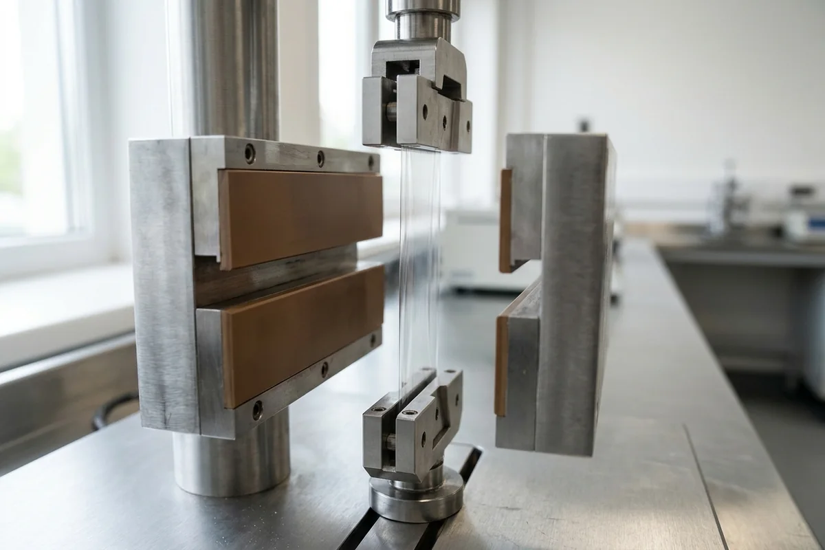
In an instrumented hot tack tester, a film strip is clamped between an upper grip connected to a force transducer (load cell) and a lower grip connected to a servo peeling actuator. The specimen loop is inserted between flat heated sealing bars for a programmed dwell time at set temperature and pressure. Once the jaws open and the programmed delay timer expires, the actuator separates the grips at a controlled speed and records peak force. Within that automated sequence, ASTM F1921 §1.3 and Cell Instruments’ ASTM F1921 technical application note distinguish the two variations by two factors:
- Grip separation rate during the peel pull.
- Whether the machine generates a cooling curve of warm-seal strength plotted against cooling time at a given temperature (Method A) or records the maximum force observed following a selected delay time across a temperature sweep (Method B).
Rule of thumb: If the packaging machine’s jaw-opening-to-product-impact interval is already measured and fixed, specify ASTM F1921 Method B at that exact delay time across your temperature sweep; if filler drop phasing or line speed is still being tuned, run Method A (or Method B at two or three bracketed delay times such as 0.1 s, 0.2 s, and 0.4 s) because polymer crystallization shifts warm-seal strength over fractions of a second.
How to map VFFS cycle and drop timing to laboratory dwell and delay time
Match the tester’s sealing time to the packaging machine’s closed-jaw contact period (t_dwell) and match the tester’s delay time (t_delay) to the elapsed time between horizontal jaw opening and first product impact (t_impact,line). Inferring either timer from overall bagger speed in packs per minute (N) alone overestimates available sealing and cooling time, because web transport and jaw travel occupy most of the machine cycle.
On an intermittent VFFS packaging line running at N packs per minute, the total cycle period per bag (T_cycle, in seconds) is:
T_cycle = 60 / N
During each cycle, the horizontal jaws remain closed under full sealing pressure for only a fraction of the 360° machine cam or servo cycle (θ_dwell, in degrees). The closed-jaw contact time (t_dwell, in seconds) that the laboratory hot tack tester must replicate is:
t_dwell = (θ_dwell / 360°) × (60 / N)
Because film transport, jaw closing, and jaw opening consume a large fraction of T_cycle, actual jaw dwell t_dwell is only the closed-jaw fraction of the cycle (read from the jaw-closed cam/servo angle θ_dwell or directly in milliseconds from the PLC timing screen). Laboratory ASTM F1921 dwell time must match t_dwell rather than T_cycle; setting a longer dwell allows more heat to reach the seal interface and artificially lowers the apparent threshold sealing temperature.
Once the horizontal jaws open (t = t_jaw_release), the laboratory delay time is the interval before grip separation starts (t_peel_start):
t_delay,lab = t_peel_start - t_jaw_release
On the VFFS line, the freshly made bottom seal is loaded when the falling product charge strikes the seal (t_first_impact):
t_impact,line = t_first_impact - t_jaw_release
For a dense product released from rest at drop height h (in meters) above the horizontal jaws precisely when the jaws open, the vacuum free-fall transit time (t_fall, with gravitational acceleration g ≈ 9.81 m/s^2) provides an idealized baseline:
t_fall = √(2 × h / g)
Example calculation (from vacuum free-fall kinematics before accounting for filler phasing or air drag):
For h = 0.50 m, t_fall ≈ 0.32 s; for h = 0.80 m, t_fall ≈ 0.40 s
Do not rely on √(2 × h / g) without checking the machine’s PLC timing chart or high-speed video of the bag bottom. On high-speed VFFS lines, filler discharge is phased so the product slug is already falling inside the forming tube before the horizontal jaws open. If the leading edge of the product charge reaches the bottom seal 0.15 s after jaw release, testing in the laboratory at a 0.5 s delay gives the molten sealant extra time to crystallize, hiding line bursts that occur at 0.15 s. Conversely, light snacks or fine powders slowed by air resistance in the forming tube can arrive later than √(2 × h / g). Time the interval from jaw separation to first visible bag-bottom deflection and enter that value as t_delay,lab.
Why hardware geometry and heating mode shift the measured curve
Two laboratories can cite ASTM F1921 on the same roll of film and produce different temperature windows if their instruments use different seal-bar depths, coatings, or jaw-heating configurations. Thwing-Albert’s ASTM F1921 equipment overview identifies six selectable setup variables on its J&B 5000MB tester: sealing temperature, sealing time, sealing pressure, cooling (delay) time, peeling speed, and sample width. Beyond those software settings, published specifications from Thwing-Albert, Labthink, and Cell Instruments show substantial hardware differences across commercial testers.
Scroll horizontally to view all columns if needed. ↔
| Published hardware parameter | Thwing-Albert J&B 5000MB | Labthink HTT-L1 | Cell Instruments HTT-02 | Impact on seal-jaw window mapping |
|---|---|---|---|---|
| Standard seal-bar dimensions (width x depth) | 50 x 5 mm (5 x 50 mm NIPTEF-coated bars) | 100 x 5 mm sealing area | 50 x 10 mm (PTFE-coated bars) | A 10 mm deep seal band doubles the axial seal land compared with a 5 mm bar, altering heat extraction and peel profile |
| Jaw heating configuration | Symmetrical or asymmetrical; two-sided or one-sided heating | Single sealing jaw or double sealing jaw | Double-heated upper and lower jaws | One-sided heating conducts heat across both webs from one bar, shifting the apparent window to higher setpoints than two-sided heating |
| Sealing temperature range | Ambient to 260°C (500°F), PID controlled | Room temperature to 250°C (±0.2°C) | Ambient to 250°C (±0.2°C) | Verify actual surface temperature calibration across the bar width before running a sweep |
| Sealing dwell time range | 0.1 to 20 s | 0.1 to 999.9 s | 0.1 to 9999 s | High-speed VFFS dwells typically sit near the bottom of the tester range (0.1 to 1.0 s); confirm timer repeatability at short settings |
| Cooling (delay) time range | 0.1 to 999 s | Automated hot tack delay control | Programmable interval from jaw release to peel | Set directly to measured t_impact,line rather than leaving a multi-second default |
| Sealing pressure range | 0.1 to 2.0 N/mm² (6 to 8 bar air supply required) | 0.05 to 0.7 MPa (0.5 to 0.7 MPa gas supply) | 0.15 to 0.7 MPa | Record calibrated interfacial bar pressure, not the plant compressed-air line reading |
| Peel speed & force capacity | 4 to 600 mm/s (1,000 mm/s option); 0 to 45 N (225 N option) | 100 to 500 mm/min plus hot tack speed mode; 0 to 200 N (30, 50, 100 N options) | Constant speed peel; 200 N standard (30, 50, 100 N options) | Match load-cell range to warm-seal forces (often 1 to 20 N per strip width) to maintain force resolution |
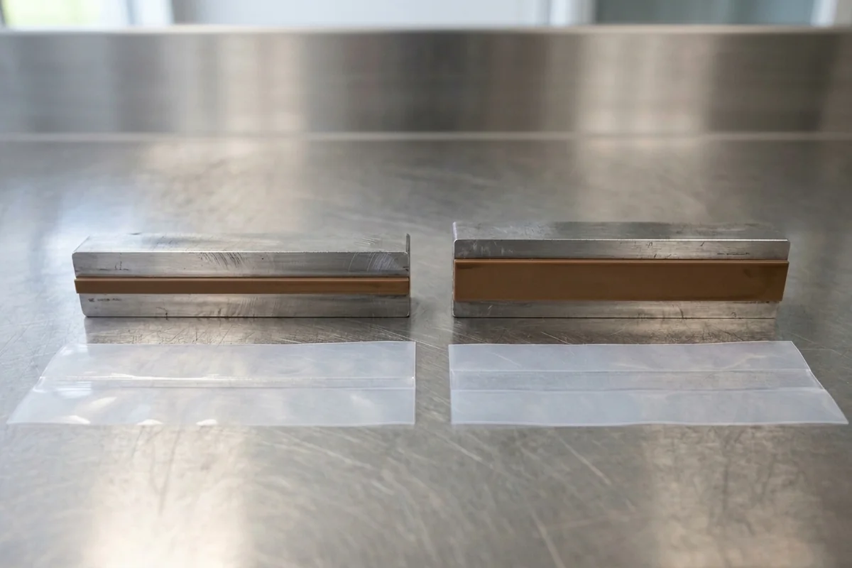
Laminate thickness and layer construction govern how rapidly heat from those bars reaches the sealant interface. Cell Instruments’ ASTM F1921 application note gives laboratory screening dwell examples by web thickness at 15 to 30 N/cm² (0.15 to 0.30 MPa) pressure: roughly 0.5 s for thin webs up to 25 µm, 1.0 s for medium webs from 25 to 64 µm, and 2.5 s for thicker laminates above 64 µm. Those screening intervals are useful when benchmarking raw resin lots in a laboratory, but they do not represent a packaging machine’s jaw window. If a >64 µm laminate runs on a high-speed VFFS bagger at a 0.1 to 1.0 s closed-jaw dwell, running the laboratory tester at 2.5 s hides the thermal lag across the outer carrier and barrier layers. Always test at the line’s closed-jaw dwell t_dwell and match one-sided or two-sided heating to the packaging machine’s jaws.
How to normalize strip width, pressure, and peel speed across reports
Convert specimen strip width, sealing pressure, and grip separation speed onto a single SI basis before comparing two hot tack curves or transferring a force target into a specification. ASTM F1921/F1921M-12(2023) §1.4 states that SI units are preferred and govern referee decisions, while inch-pound values are stated separately and are not exact equivalents.
Scroll horizontally to view all columns if needed. ↔
| Parameter | Common reporting units | Normalization formula | Worked conversion example |
|---|---|---|---|
Warm-seal force per width (f) |
N/15 mm, N/25 mm, N/25.4 mm (N/in), or N/mm | f = F_peak / w, and F(w2) = F(w1) × (w2 / w1) |
A 25.4 mm (1.00 in) strip has 25.4 / 15 = 1.693 times the seal width of a 15 mm strip; always record both raw F_peak and tested strip width w |
Interfacial sealing pressure (P) |
N/mm², MPa, N/cm², psi | 1 N/mm² = 1 MPa = 100 N/cm² ≈ 145.04 psi |
Cell Instruments’ screening range of 15 to 30 N/cm² converts to 15 / 100 to 30 / 100 = 0.15 to 0.30 MPa (0.15 to 0.30 N/mm²) |
Grip separation (peel) speed (v_peel) |
mm/s (hot tack) vs. mm/min (cooled peel) | v_mm/min = v_mm/s × 60 |
A hot tack peel speed of 200 mm/s equals 200 × 60 = 12,000 mm/min, which is 24 times faster than a 500 mm/min cooled seal peel |
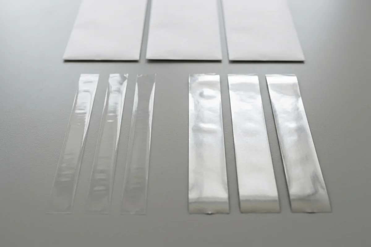
Intertek’s ASTM F1921 procedure summary and Labthink’s HTT-L1 specifications list three standard specimen widths: 15 mm, 25 mm, and 25.4 mm (1.00 in), with specimen lengths typically 250 mm minimum (Thwing-Albert J&B 5000MB) to 30 to 35 cm (12 to 14 in, Intertek) to span the sealing jaws and grip loop. Because a 25.4 mm strip is 1.693 times wider than a 15 mm strip, comparing raw Newtons without dividing by strip width w scales raw force by 1.693 times at identical seal strength per unit width.
Keep hot tack peel speeds strictly separate from cooled packaging seal strength speeds. As detailed in our guide to comparing flexible packaging film specifications, a typical hot tack peel speed of 200 mm/s (12,000 mm/min) is 24 to 120 times faster than the 100 to 500 mm/min grip speeds used for cooled ASTM F88 seal testing. Because molten polymers are viscoelastic, peel force changes significantly with strain rate; never copy a force value from a 200 mm/s hot tack curve into a cooled heat-seal specification row.
How to read the hot tack curve and define the seal-jaw temperature window
Read three numbers from a line-matched hot tack temperature sweep: the Threshold Sealing Temperature (T_threshold), the Peak Hot Tack Force (F_peak at T_peak), and the upper window boundary (T_upper), which together define the usable Hot Tack Temperature Range (ΔT_window). Both Intertek’s ASTM F1921 summary and Thwing-Albert’s J&B 5000MB documentation define these outputs along with the physical failure mode at each temperature step.
When warm-seal force per unit width f(T, t_delay) is plotted on the vertical axis against sealing jaw temperature T on the horizontal axis at fixed t_dwell, pressure, strip width, and peel speed, the usable jaw temperature window is:
ΔT_window = T_upper - T_threshold (where f(T, t_delay) ≥ f_req)
Here f_req = F_req / w is the minimum warm-seal force per unit width required to hold the product drop on your specific bagger. There is no universal Newton-per-millimeter target in ASTM F1921; f_req depends on product mass, drop height, bag diameter, and jaw profile, and is established by correlating laboratory curves with filled-bag trials.
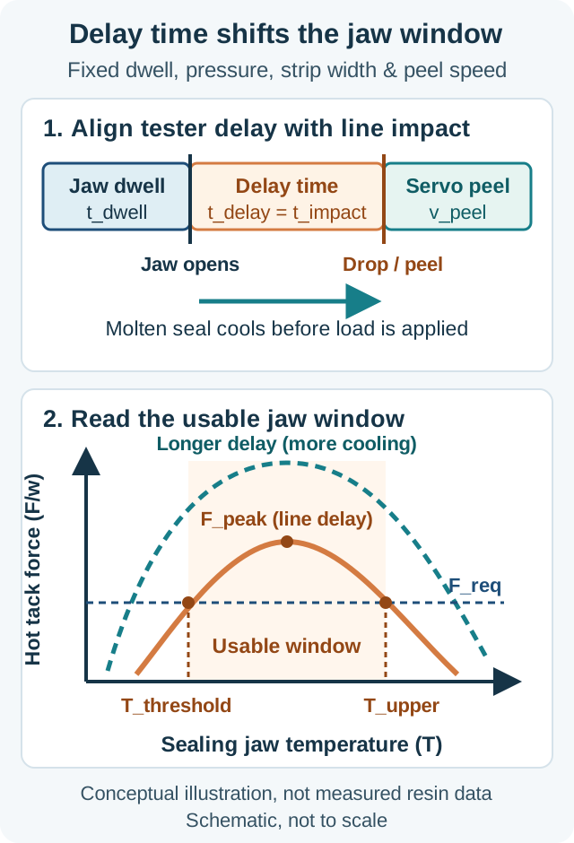
Across the temperature sweep, inspect the specimen failure mode (classified in the same terms used in ASTM F88 and summarized in Cell Instruments’ ASTM F1921 note) alongside the force reading to locate each window boundary:
- Below
T_threshold(insufficient interfacial diffusion): polymer chains across the sealant interface have not entangled completely duringt_dwell. The warm seal peels cleanly at the interface (adhesive peel failure) belowf_req. Do not confuseT_thresholdon a warm F1921 curve with cooled seal initiation temperature (SIT) prepared under ASTM F2029-16(2021); a sealant can reach a low cooled SIT after cooling and crystallization while still failing under immediate warm load. - Around
T_peak(cohesive melt strength peak): interfacial fusion is complete while the molten polymer retains sufficient melt viscosity and chain entanglement to resist separation, yieldingF_peak. - At and above
T_upper(melt thinning, squeeze-out, or web distortion): as jaw temperature rises pastT_peak, sealant viscosity drops sharply. Under bar pressure, molten polymer squeezes out of the seal zone, thins the seal web, or stretches and breaks during peeling. On mono-material PE or PP laminates where the outer carrier and inner sealant share similar melting ranges, the upper window edgeT_upperis frequently capped by outer-layer shrinkage, wrinkling, or jaw sticking even before warm force drops belowf_req.
Per ASTM F2029-16(2021) §4.2, laboratory heat-sealer curves serve as a starting bracket rather than direct validation of full-scale production equipment. Smooth, flat PTFE-coated laboratory bars transfer heat more uniformly than serrated VFFS jaws with knife slots, back-seal overlaps, and product dust. Use the laboratory ΔT_window to screen candidate PE and LLDPE sealant structures and set the initial trial bracket on the packaging line, then verify both warm drop survival and cooled ASTM F88 seal strength on finished packs.
Common alignment failures and checklist before requesting lab curves
Most discrepancies between a laboratory hot tack report and packaging-line seal performance trace back to an unaligned delay timer, unnormalized strip width, or unstated jaw heating mode.
Scroll horizontally to view all columns if needed. ↔
| Observed mismatch or report gap | Physical mechanism & line consequence | Corrective setup or audit action |
|---|---|---|
| Lab delay time is longer than VFFS jaw-open-to-drop timing (for example, 0.5 s lab delay vs. 0.15 s machine impact) | Extra cooling time lets the laboratory specimen crystallize before peeling, overstating warm-seal force; bottom seals burst on product impact | Measure jaw release to first bag-bottom deflection on the line and re-run ASTM F1921 Method B at that delay |
Delay or dwell is calculated as 60 / N from packs/min alone |
Total cycle time includes film advance and jaw travel; actual dwell and drop intervals are fractions of T_cycle |
Calculate closed-jaw dwell from cam/servo angle ((θ_dwell / 360°) × (60 / N)) and time product drop separately |
| Supplier A reports force on a 15 mm strip while Supplier B reports on a 25.4 mm (1.00 in) strip | A 25.4 mm strip is 1.693 times wider than a 15 mm strip, reporting 1.693 times higher raw Newton values at equal seal strength per unit width | Divide peak force by tested width w to compare in N/mm, or scale to a single reference strip width |
| Laboratory uses two-sided heated bars while the packaging station heats only one jaw (or vice versa) | Conducting heat through both webs from one side requires higher bar temperature or longer dwell to reach the interface | Configure the hot tack tester for one-sided or asymmetrical heating to match the production station |
| Compressed-air supply pressure (0.5 to 0.7 MPa or 6 to 8 bar) is written in the sealing-pressure cell | Pneumatic cylinder ratio means line supply pressure does not equal interfacial bar contact pressure (N/mm²) | Record calibrated interfacial jaw contact pressure in N/mm² (MPa) alongside seal-bar dimensions |
| Warm F1921 peak force (200 mm/s) is copied into a cooled ASTM F88 specification row (100 to 500 mm/min) | Polymer state (molten vs. crystallized) and peel rate (24 to 120 times) differ completely | Keep ASTM F1921 warm curves and ASTM F2029/F88 cooled curves in separate specification columns |
Before requesting a laboratory hot tack curve from a film supplier or third-party testing lab, or before placing two candidate laminate reports side by side, complete the alignment record below.
Scroll horizontally to view all columns if needed. ↔
| Alignment field | Target machine or specification entry | Laboratory ASTM F1921 report check |
|---|---|---|
| 1. Film structure & sealant | Full layer construction, total gauge (µm), sealant resin family, and sealant thickness (µm) | Confirm tested lot and whether corona/treatment or slip additives match production rollstock |
| 2. ASTM F1921 method & instrument | Specify ASTM F1921/F1921M-12(2023) Method A (cooling curve) or Method B (fixed-delay temperature sweep) | Record tester make/model, load-cell capacity, and confirm automated instrumented execution |
| 3. Jaw geometry & heating symmetry | Production jaw land depth, serration profile, and one-sided vs. two-sided heating | Record lab bar width x depth (50 x 5 mm, 100 x 5 mm, or 50 x 10 mm), PTFE coating, and heated faces |
4. Closed-jaw dwell time (t_dwell) |
PLC closed-jaw contact time or (θ_dwell / 360°) × (60 / N) (in seconds) |
Verify laboratory sealing timer matches t_dwell rather than a generic thickness screening table |
5. Interfacial sealing pressure (P) |
Estimated or calibrated jaw contact pressure in N/mm² (MPa) | Convert N/cm² or psi to N/mm² (1 N/mm² = 1 MPa = 100 N/cm²) and separate from air-line pressure |
6. Delay time to impact (t_delay) |
Measured interval (in seconds) from horizontal jaw release to first product impact (t_impact,line), plus drop height h and pack mass |
Confirm laboratory delay time from jaw opening to grip separation matches t_impact,line |
| 7. Specimen width & peel speed | Target reporting width (15 mm, 25 mm, or 25.4 mm) and grip separation rate in mm/s | Normalize force to N/mm or matched strip width and verify peel speed in mm/s (mm/s × 60 = mm/min) |
| 8. Window metrics & failure modes | Required warm-seal load threshold (f_req) and acceptable upper-temperature appearance |
Record T_threshold, F_peak (T_peak), T_upper, ΔT_window, and failure mode (adhesive, cohesive, delamination, distortion) at each step |
When preparing a technical handoff for a supplier or testing laboratory, send four core inputs: (1) your target machine jaw temperature range and heating configuration (one-sided versus two-sided), (2) closed-jaw dwell time (t_dwell), (3) measured jaw-opening-to-product-impact delay time (t_delay), and (4) the complete film layer structure with total and sealant thicknesses.
Technical references
- ASTM F1921/F1921M-12(2023), Standard Test Methods for Hot Seal Strength (Hot Tack) of Thermoplastic Polymers and Blends Comprising the Sealing Surfaces of Flexible Webs, public scope and significance/use (§1.1 to §1.6, §5.1).
- ASTM F2029-16(2021), Standard Practices for Making Laboratory Heat Seals for Determination of Heat Sealability of Flexible Barrier Materials as Measured by Seal Strength, public scope and significance/use (§1.1 to §1.8, §4.1 to §4.2).
- Intertek Testlopedia, Hot Seal Strength ASTM F1921, laboratory procedure summary, specimen dimensions, and curve output definitions.
- Thwing-Albert Instrument Company, ASTM F1921 Equipment Overview and J&B Hot Tack Tester Model 5000MB published product specifications.
- Labthink Instruments, HTT-L1 Hot Tack Tester published technical specifications.
- Cell Instruments, HTT-02 Hot Tack Tester product specifications and ASTM F1921 Hot Tack Strength Testing technical application note (Method A cooling-curve versus Method B delay-time overview and failure mode classification).
Continue reading
Related articles
Seal Strength Tester Setup: ASTM F88 Tail Support (Technique A, B, C) and Acceptance Records
Configure a seal strength tester under ASTM F88/F88M-23 by locking tail support (Technique A, B, or C), strip width, and Clause 10.1 acceptance records.
OTR Tester Setup: ASTM D3985 Dry vs Controlled-Humidity (ASTM F1927) Conditions
Configure an oxygen transmission rate tester for dry ASTM D3985 and humidified ASTM F1927 flat barrier film evaluation.
WVTR Tester Method Selection: ASTM F1249 Infrared vs Gravimetric Cup (ASTM E96)
Choose a water vapor transmission rate tester by method, both-side humidity and usable range. Compare ASTM F1249 infrared with ASTM E96 cup testing.