
How to Choose Flexible Packaging Film: A Step-by-Step Selection Guide
An end-to-end engineering guide to selecting flexible packaging films: product barrier risks, machine kinematics, substrate structures, and trial verification protocols.
Choosing the right flexible packaging film is a balancing act between product preservation, machine runnability, and cost per good pack. Selecting a film solely based on supplier marketing or generic “best film” rankings routinely results in line jams, channel leakers, or unnecessary barrier over-engineering.
A structured selection process starts with the degradation mechanisms of your product, matches film physics to your packaging equipment, specifies an appropriate multi-layer laminate, and verifies performance on the actual packaging line.
Scroll horizontally to view all columns if needed. ↔
| Input or item | Typical value or source | Why it matters |
|---|---|---|
| Shelf-life target | Your product and market requirement, in months | Sets the barrier the finished pack must deliver |
| OTR / WVTR limits | Derived from product sensitivity; tested per ASTM D3985 / F1249 at stated conditions | Selects the barrier layer |
| Machine and format | Make, model, sealing method and planned speed | Sets hot tack, COF and stiffness needs |
| COF range | Machine supplier’s film spec or a film that already runs; ASTM D1894 | Controls tracking on forming parts |
| Seal strength minimum | Your specification, with strip width; ASTM F88 | Supports closure, not leak-tightness |
| Leak test | Method chosen for your pack, e.g. ASTM D3078 for packs with headspace | Screens finished packs for leaks |

- Define product risks and shelf life.
- Match the format and machine.
- Specify layer functions and gauges.
- Agree converting and compliance records.
- Trial the film and verify filled packs.
Step 1: Quantify Product Sensitivity and Shelf-Life Threats
Before evaluating film catalog data sheets, determine the environmental threats that shorten your product’s shelf life.
- Oxygen Degradation (OTR): Oxidation causes rancidity in fats, degradation of essential oils, and flavor loss in snacks, nuts, and roasted coffee. Set the maximum Oxygen Transmission Rate (OTR) from your product’s shelf-life target and the oxygen it can tolerate, and state the test conditions (temperature and humidity) with the number. Oxygen-sensitive products usually point to foil, metallized or EVOH structures; see OTR values by material for the relative ranges.
- Moisture Transfer (WVTR): Crispy products (crackers, chips, dry powders) need a low Water Vapor Transmission Rate (WVTR) to prevent sogginess or caking; derive the limit from how much moisture the product can gain before it fails, at the storage conditions you expect. Conversely, fresh produce requires breathable films to prevent condensation and anaerobic spoilage. Review the moisture barrier guide for measurement test standards (ASTM F1249 vs ASTM E96).
- Light and UV Sensitivity: Photosensitive ingredients (vitamins, dairy fats, colored pigments) degrade under ambient retail fluorescent and natural light. Where opaque protection is required, specify metallized PET (met-PET) or solid aluminum foil layers.
- Puncture and Abrasion Threats: Sharp edges (bone-in meats, dried pasta, dehydrated snacks) require high tear and puncture resistance. Refer to the puncture resistance testing guide for dart drop and slow-rate penetration criteria.
Step 2: Match Packaging Format and Machine Kinematics
A film formulation that runs smoothly on a slow rotary pouch machine can fail completely on a high-speed vertical form-fill-seal (VFFS) machine.
Scroll horizontally to view all columns if needed. ↔
| Packaging Machine Type | Critical Film Mechanical Requirements | Common Failure Modes If Mismatched |
|---|---|---|
| VFFS (Vertical Form Fill Seal) | High hot tack, wide sealing window, controlled elongation | Bottom seal blowouts during product drop, film stretching over forming collar |
| HFFS Flow Wrapper | Low and consistent coefficient of friction (COF), rapid heat transfer | Fin-seal slippage, package necking, thermal distortion at high feed speeds |
| Premade Pouch Bagger | High web stiffness (flexural rigidity), flat lay, uniform zipper sealability | Pouch sagging in pickup fingers, pouch mouth distortion during air jet opening |
| Vacuum / Gas Flush (MAP) | Hermetic seal integrity, puncture resistance, low flex-crack pinholing | Slow leakers across folds, loss of modified atmosphere head space |
Detailed machine compatibility constraints for individual baggers and wrappers are documented in our machine compatibility directory.
Step 3: Select Substrate Architecture and Layer Construction
Flexible packaging films are rarely single polymers; they are engineered multi-layer laminates where each ply performs a dedicated functional role:
- Outer Print & Thermal Carrier Layer: Choose PET, BOPP or BOPA/nylon and its gauge from the required print support, thermal stability and strength, then verify the actual construction. This layer accepts rotogravure or flexographic printing and withstands the hot sealing jaws without melting. Compare properties in our PET vs BOPP film analysis.
- Intermediate Barrier Core:
- Aluminum foil, gauge set by the structure specification: Intact foil lets practically no oxygen or water vapor through, which makes it the highest-barrier layer in aluminum foil laminates. That is a property of undamaged foil, not of the finished pack: thin foil can contain pinholes, forming and handling can crack it (ASTM F392 is the practice for flex-conditioning barrier materials before testing for pinholes), and oxygen and moisture also enter through seals, folds and closures. Specify and test the barrier of the converted, filled pack, not just the foil.
- Metallized PET / OPP: Vacuum-deposited aluminum layer offering high barrier with superior flex resistance.
- EVOH (Ethylene Vinyl Alcohol): High-clarity gas barrier coextruded within polyethylene structures, sensitive to moisture unless protected by outer polyolefin layers.
- Inner Sealant Web: Choose the gauge and grade of blown or cast PE (LDPE, LLDPE or metallocene PE), or a validated retort-grade CPP where the process requires it, from seal strength, integrity and line-trial evidence. The sealant layer must melt cleanly, flow around contaminants or wrinkles, and form a hermetic bond at target line speeds.
For companies prioritizing circular economy compliance, consult our mono-material recyclable packaging guide to understand the engineering trade-offs of all-PE and all-PP structures.
Step 4: Define Functional Converting Specifications
When issuing a Request for Quotation (RFQ) to flexible packaging converters, specify functional tolerances rather than vague commercial descriptors:
- Coefficient of Friction (COF): Specify a kinetic COF range for the surface that contacts the forming collar or plates (film-to-metal) and for film-to-film, measured per ASTM D1894, and take the range from your machine supplier’s film specification or from a film that already runs well on the line. Too low a COF can cause tracking slippage and telescoping rolls; too high can cause drag and sticking on forming parts. See coefficient of friction.
- Seal Initiation Temperature (SIT): Determine the lowest temperature at which the sealant reaches the minimum seal strength you have specified (state the strength and strip width). Lower SIT can allow faster line speeds and less heat on heat-sensitive products. Consult seal initiation temperature methods.
- Gauge Uniformity: Agree a total thickness tolerance across the roll width with the converter and how it is measured. Variations in thickness lead to uneven roll tension, web wander, and leakers on horizontal fin seals. Review standard units in film thickness explained.
- Roll Unwind Direction: Clearly define rollstock winding geometry (e.g., unwind direction #3 or #4, core size 76 mm vs 152 mm, maximum roll outside diameter).
Step 5: Execute Line Trials and Quality Verification
Never transition commercial production to a new film structure without a structured, empirical validation protocol:
- Pre-trial Benchtop Checks: Measure gauge with a calibrated micrometer, verify COF on a laboratory sled, and review supplier Certificate of Analysis (CoA) batches against how to compare flexible packaging film specifications.
- Trial Run Setup: Run a pilot at several speeds up to your normal production speed (for example 50%, 75% and 100%), with a pack count agreed with your quality team so that the leak results mean something. Record jaw temperature, seal pressure, dwell and line throughput.
- Integrity and Seal Testing: These two checks answer different questions.
- Leak test, such as bubble emission (ASTM D3078): Filled packs are submerged in a vacuum chamber and watched for bubbles. ASTM scopes this method to flexible packages that contain headspace gas and to gross leaks: very small leaks may not show, and product can plug a leak path. Vacuum packs without headspace need a different method, so choose and validate the leak test for your pack, contents and the leak size you need to detect.
- Seal strength (ASTM F88): Measures the force needed to separate a strip containing the seal and records the failure mode. A minimum seal strength supports closure, but a strong seal can still leak through a wrinkle or product in the seal, so it does not replace the leak test. Set the minimum and the strip width in your specification; see seal strength.
- Leaker and Scrap Rate: Compare reject rates with your current film’s baseline. Whether a scrap increase cancels a film discount depends on how much of the pack’s cost is film. Hypothetical example: if film is 5% of the cost of a finished, filled pack, a 10% film discount saves about 0.5% of pack cost, and an extra 0.5 percentage points of scrapped finished packs costs about the same. Run the numbers with your own cost split, as explained in when cheaper film costs more.
Flexible Packaging Film Selection Checklist
Use this checklist during initial project scoping and converter supplier reviews. Fill the agreed test conditions; values such as 23°C/0% RH for OTR or 38°C/90% RH for WVTR would be example conditions, not requirements for every project:
Scroll horizontally to view all columns if needed. ↔
| Checkpoint | Parameter / Question | Requirement / Record Value | Verified |
|---|---|---|---|
| Shelf-Life Goal | Required product shelf life (months) | Target: ____________ | [ ] |
| Gas Barrier | Maximum OTR, cc/m²/24hr; temperature: ____; RH: ____; conditioning: ____ | Method/version and limit: ____ | [ ] |
| Moisture Barrier | Maximum WVTR, g/m²/24hr; temperature: ____; RH: ____; conditioning: ____ | Method/version and limit: ____ | [ ] |
| Packaging Machinery | Make, model, and rated line speed (ppm) | Model: ____________ | [ ] |
| Seal Mechanism | Heated bar, rotary jaw, ultrasonic, or impulse | Temp range: ____________ | [ ] |
| Structure Definition | Total gauge and individual layer thicknesses (µm) | Target: ____________ | [ ] |
| COF Target | Kinetic film-to-metal and film-to-film friction (ASTM D1894) | Range: ____________ | [ ] |
| Regulatory Status | Destination, use conditions; compliance declaration and supporting documents | Document/version/review: ____ | [ ] |
| Batch CoA | Lot identity and reported checks against the agreed specification | Lot/report/date: ____ | [ ] |
| Production Trial | Pilot run at planned line speeds; pack count agreed | Leak test method and leakers found: ____ | [ ] |
If a trial reveals recurring defects, use the film-problem investigation guide to preserve samples and identify the next check.
Working through these steps gives you a specification and trial record you can compare suppliers against. It does not by itself prove shelf life: confirm that with leak testing of filled packs and shelf-life testing of your product in the chosen structure (shelf life and packaging).
Frequently asked questions
What does a certificate of analysis contain?
For a film purchase, check the batch identity and the methods, limits and results actually supplied; flag missing fields. Keep the separate compliance declaration and its supporting evidence with it. A CoA does not automatically establish regulatory suitability for a destination or use.
Sources
- ASTM F88/F88M-23, Standard Test Method for Seal Strength of Flexible Barrier Materials (scope and significance), accessed October 7, 2026.
- ASTM F392/F392M-21, Standard Practice for Conditioning Flexible Barrier Materials for Flex Durability (significance and use), accessed October 7, 2026.
- ASTM D3078-02, Standard Test Method for Determination of Leaks in Flexible Packaging by Bubble Emission (scope, 2008 reapproval page), accessed October 7, 2026.
- ASTM D1894-24, Standard Test Method for Static and Kinetic Coefficients of Friction of Plastic Film and Sheeting, accessed October 7, 2026.
- Sterilization Packaging Manufacturers Council, Impact on barrier of pinholes in the foil layer of a lamination, accessed October 7, 2026.
- Regulation (EU) No 10/2011, Articles 15 and 16: declaration of compliance and supporting documents, consolidated July 14, 2026; EU food-contact plastics scope, reviewed October 9, 2026.
These sources define the test methods; the specification ranges in this guide are left for you to set with your converter and machine supplier.

Continue reading
Related articles
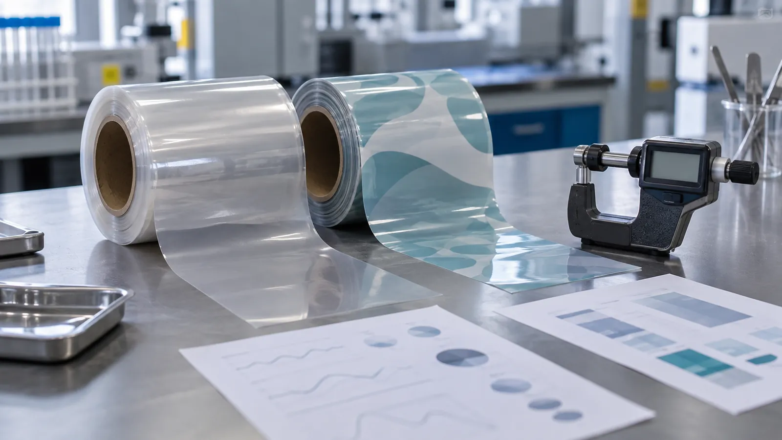
How to Compare Flexible Packaging Film Specifications
Separate hard requirements from preferences, normalize units and test conditions, and compare the full package before choosing a film.
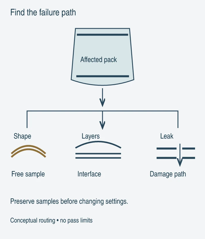
Flexible Packaging Film Problems: A Troubleshooting Guide
Film defects can cause scrap, leaks and repeat downtime. Locate the failure and preserve comparison samples before choosing a test or changing materials.
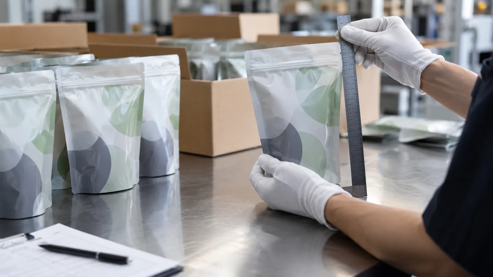
First-Order Risk Checklist for Printed Pouches and Rollstock
A compact checklist for controlling specification, payment, quality and shipment risk on a first order of printed pouches or rollstock.